Stereo Shuffling | New Approach – Old Technique
A technique that has been known but almost unused for over 30 years. This is the stereo ‘shuffler’. Although many recording engineers and studios don’t realise it they already have the equipment to produce a marked improvement in the stereo quality of many of their recordings.
What is a shuffler, and how come you didn’t know you had one?
The basic idea of the shuffler goes back to Alan Blumlein’s invention of modern stereo in 19311. (His British Patent 394,325 repays detailed study as perhaps still the best source text on how stereo works.) Blumlein conceived stereo not just as a left (L) and right (R) speaker signal but also in terms of a sum signal M (= L+R) and a difference signal S (=L–R). The letters M and S stand for ‘mid’ and ‘side’ signals (as in the M-S microphone technique): M is the signal containing information about the middle of the stereo stage, whereas S only contains information about the sides – since S=0 for a central signal.
Given M and S, the original left and right signals can be recovered by a second sum-and-difference operation, via 2L=M+S and 2R=M–S. Blumlein was able to modify the width of the stereo images of coincident- microphone recordings by increasing (or decreasing) the gain of the S signal relative to M before recovering the left and right signals (Fig 1)
An increase in the relative gain of S increased width, whereas a decrease of S gain decreased width. In view of the fact that width control was known in 1931, it is strange that it is still not available on most modern stereo equipment. One of Blumlein’s many discoveries’ was that increased width could yield stereo images beyond the left and right speakers. This useful discovery would permit one to pan sounds over a wider stage than normally used in today’s studio. There is no reason why panpots should not be designed to cover such an increased stage width – yet I am unaware of a single mixer in which this is actually done.
Essentially, in order to widen the stereo image at a given frequency, one increases the gain at that frequency in channel 2 of the graphic equaliser, possibly slightly decreasing the gain at that frequency in channel 1 in order to retain a flat frequency balance in the resulting overall sound. Similarly, to decrease the width at a given frequency, one reduces that frequency’s gain in channel 2, increasing it slightly in channel 1 to maintain the overall frequency balance.
https://www.audiosignal.co.uk/Resources/Stereo_shuffling_A4.pdf
To change the overall width, one similarly increases or decreases the overall gain in channel 2 of the graphic equaliser of Fig 2. Moreover, the processing system of Fig 2 is a powerful technique of reducing various problems with stereo. For example, reducing the width at low frequencies makes vinyl records easier to cut, since low frequency S signals at a high level are hard to cut. Noise from FM stereo reception can be reduced by cutting the width around 7kHz, since S channel noise around this frequency contributes most to the perceived noise. Stereo mics picking up thumps from transmitted floor vibrations can often yield more thump-free recordings by selective bass filtering of the S channel.
Experimenting with width control and shuffling yields other good reasons why width control should be confined to the lower frequencies. Given that beyond-the-speaker images have anomalous localisation low frequencies do seem to localise quite reliably beyond the loudspeakers. So, if we increase the width only of lower frequencies (say below 600Hz or so), those low frequency signal components that do localise well are widened, while those at higher frequencies are retained in their usual easy-to-localise positions. Here the different frequency components of sounds are no longer in precisely the same position. We shall, for convenience, adopt David Griesinger’s term ‘spatial equalisation’ to describe width increase below about 600Hz.
One thing that spatial equalisation (bass width increase below 600Hz) undoubtedly does is give all the sense of increased spaciousness that normal width increase can give but without the gross anomalies that the latter can give at higher frequencies. It appears that the sense of spaciousness in stereo recordings largely depends on the directional handling of bass frequencies. This is very evident on, say, stereo recordings of audience applause in a live acoustic. The use of spatial equalisation can give a sense of being enveloped in the audience, even though there is no obvious change in the high- frequency imaging. The lower frequency components of the clapping seem to be enough to create a sense of being almost there among the audience.
On many recordings, spatial equalisation does not only improve the sense of spaciousness but can also improve the stereo imaging heard by listeners sitting away from the stereo seat. Spatial equalisation seems most beneficial on stereo recordings on which the sense of space is inadequate. On recording techniques capturing a good sense of space (eg spaced omnis and – in good acoustics – Blumlein crossed figure-of-eights) the processing is often superfluous, and can sometimes even give exaggerated spaciousness.
The basic idea is to use a mixer having a phase- inverting stereo signal path, which we shall term the ‘processing signal path’. In many mixers, this can be provided by two of the input channels plus a suitable stereo output bus or headphone outputs.
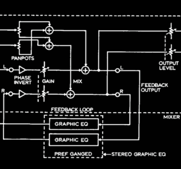
Besides the processing path which is fed back as described, the mixer also needs other stereo inputs mixed into the processing path, and a main stereo output subject to its own gain control (Fig 6 – in the Realistic mixer, any other input can be used, and the main output is used for outputting the shuffled signal).
One then mixes the stereo from other inputs, which is to be processed, into the fed-back signal path (Fig 6). The effect of the external feedback loop is to modify the stereo. For signals identical in both input channels (ie central mono or M), due to the inverting property of the processing signal path, the feedback is negative feedback, so that the M gain is reduced. For signals opposite in phase in the two channels (ie the S signal) the feedback is positive since the fed back signal adds to the signal in the other channel rather than cancelling it – this is due to the signal in the other channel being in opposite phase, so being in phase with the inverted fed back signal from the other channel. Thus the S gain is increased. As a result, as one turns up the gain in the processing signal path (by stereo-ganged gain controls at its input or output) the width is increased – up to the point where the positive feedback becomes unstable.
If one now inserts a stereo graphic equaliser into the feedback path (assuming the equaliser is not phase inverting – if the equaliser phase inverts, then a non- inverting processing signal path should be used) one has the possibility of varying the amount of feedback with frequency (Fig 7). Unfortunately, the equaliser will have some gain at all frequencies (even at maximum cut), so will tend to widen the image at all frequencies – this is not usually wanted or desirable.
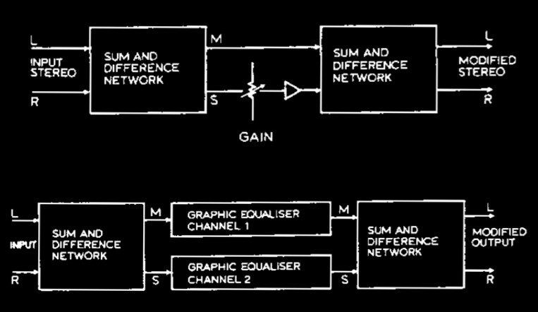
Fig 1: Blumlein’s sum-and-difference width control
Fig 2: Sum-and-difference shuffling system
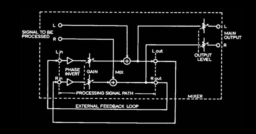
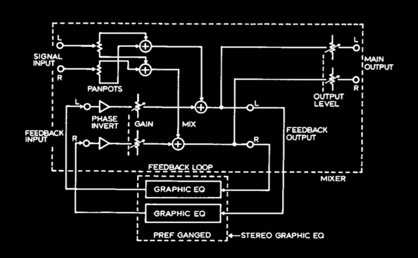
Fig 6: Stereo widening control implemented by feedback around a mixer.
The phase inversion and feedback can be anywhere in the feedback or processing signal path
Fig 7: Complete shuffling system based on Fig 6 plus stereo graphic equaliser (preferably with ganged controls). Panpots in the main signal inputs compensate for
the basic widening effect of the feedback loop
Get more more infos by reading the complete article at this link:
https://www.audiosignal.co.uk/Resources/Stereo_shuffling_A4.pdf

- Fly High Waves Sounds ™


